圖1. Microstructures of the Co-10Al-3Nb alloy after aging at 700°C for 168 h.
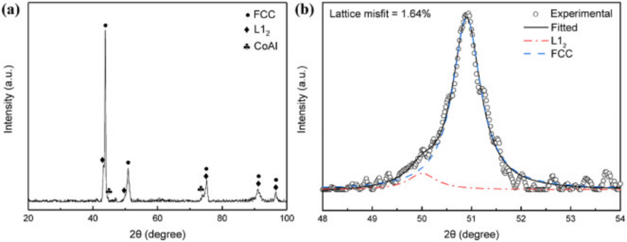
圖2. The X-ray diffraction patterns of the Co-10Al-3Nb alloy aged at 700°C for 168 h.
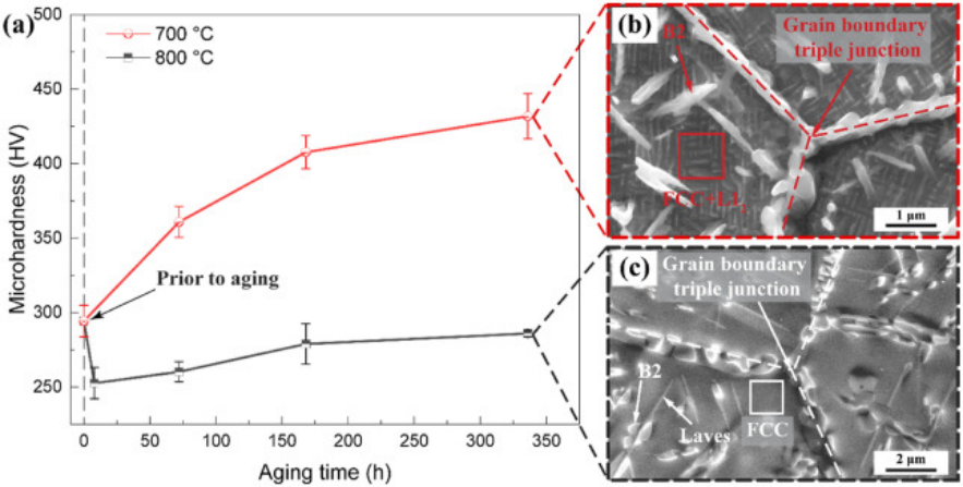
圖3. Temporal microhardness evolutions of the ternary Co-10Al-3Nb alloy aging at 700°C and 800°C, respectively.
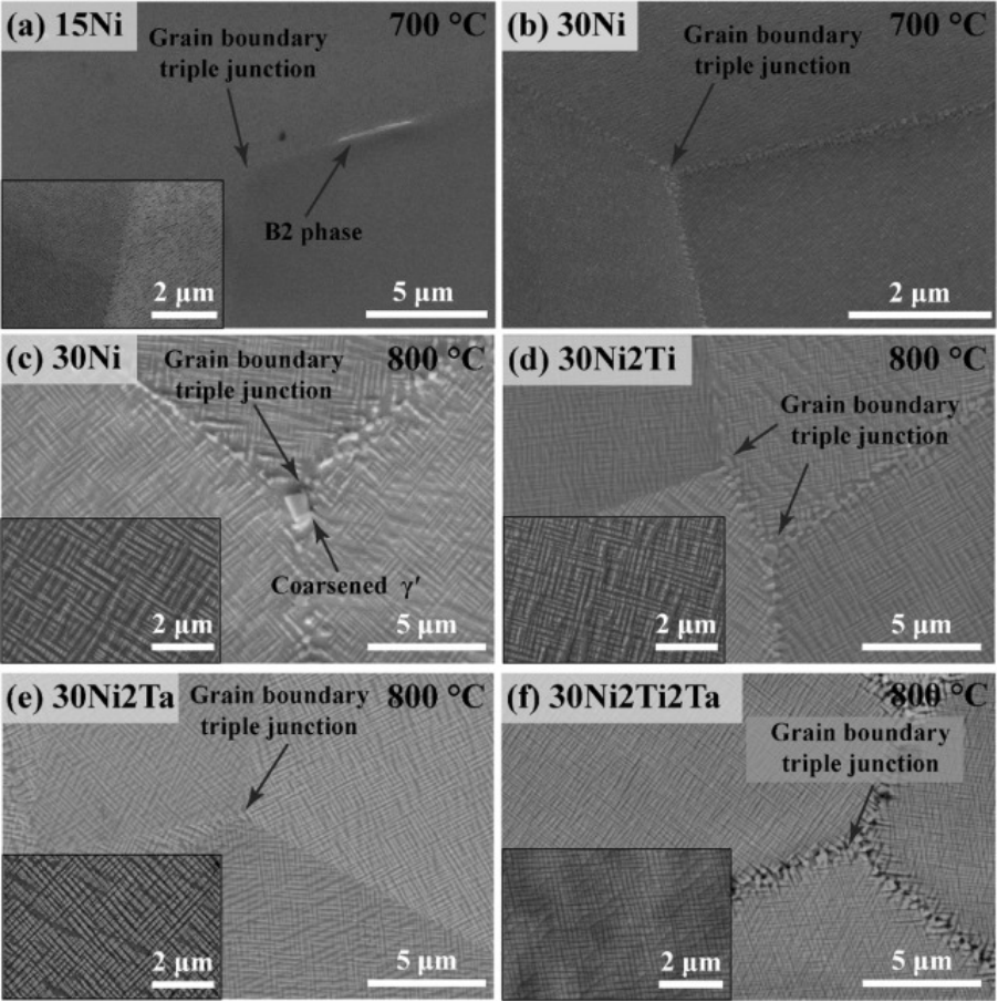
圖4. Representative SEM micrographs of grain boundary triple junction region of the (a) Co-15Ni-10Al-3Nb (15Ni) and (b) Co-30Ni-10Al-3Nb (30Ni) alloys after aging at 700°C for 168 h. Representative SEM micrographs of grain boundary triple junction region of the (c) Co-10Al-3Nb-30Ni (30Ni), (d) Co-10Al-3Nb-30Ni-2Ti (30Ni2Ti), (e) Co-10Al-3Nb-30Ni-2Ta (30Ni2Ta), and (f) Co-10Al-3Nb-30Ni-2Ti-2Ta (30Ni2Ti2Ta) alloys after aging at 800°C for 168 h.
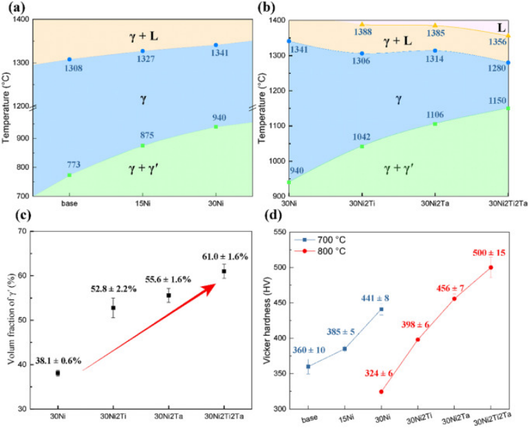
圖5. (a) The γ′-solvus and γ-solidus temperatures of the base, 15Ni, and 30Ni alloys. (b) The γ′-solvus, γ-solidus, and liquidus temperatures of the 30Ni, 30Ni2Ti, 30Ni2Ta, and 30Ni2Ti2Ta alloys. (c) The volume fraction of the γ′ phase among the Co-Al-Nb-based alloys at 800°C. (d) Microhardness evolutions of the Co-Al-Nb-based alloys after aging at 700 and 800°C for 168 h.
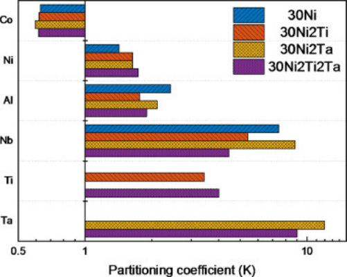
圖6. Elemental partitioning coefficients of the multicomponent Co-rich alloys, showing Co partitioned to the γ matrix phase, whereas Ni, Al, Nb, Ti, and Ta partitioned to the γ′ precipitates.
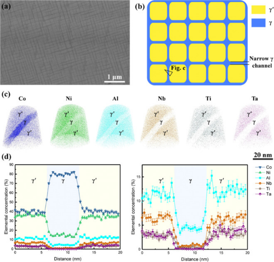
圖7. (a) SEM micrograph of the 30Ni2Ti2Ta alloy and (b) corresponding schematic diagram, showing that high-density γ′ precipitates divide the γ phase into nanoscale channels. (c) Ion maps of reconstructed nanotips by APT. (d) Proximity histograms across the γ/γ′ interfaces, showing distinctly different elemental compositions between the γ and γ′ phases.
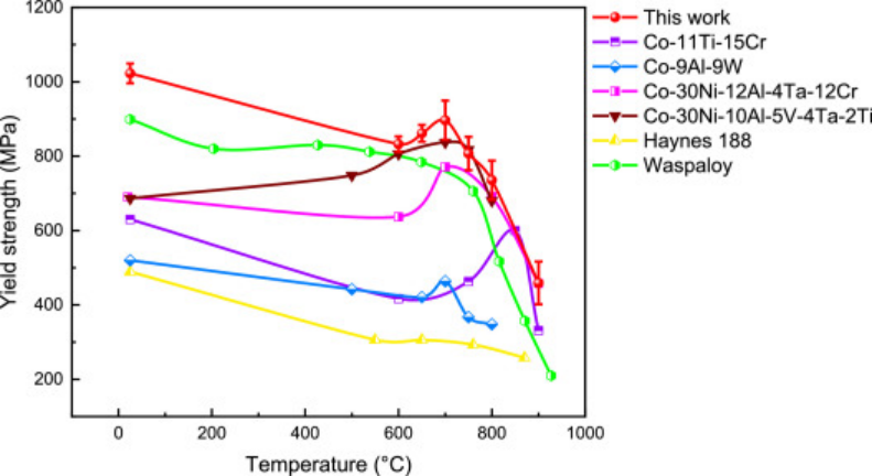
圖8. The plots between the yield strength and deformation temperature of the 30Ni2Ti2Ta alloy, together with other L12-strengthened Co-based alloys (Co-11Ti-15Cr, Co-9Al-9W, Co-30Ni-12Al-4Ta-12Cr, and Co-30Ni-10Al-5V-4Ta-2Ti alloys), a conventional carbide-hardened Co-based alloy (Haynes 188), and a commercial Ni-based superalloy (Waspaloy).
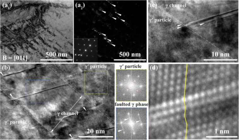
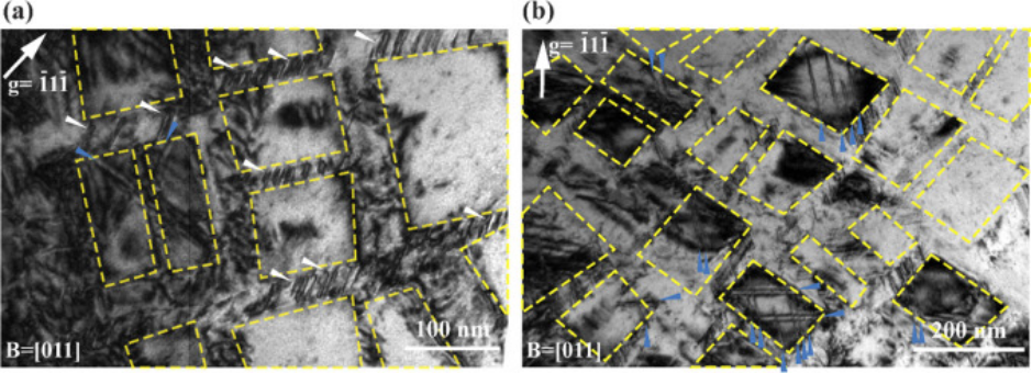
圖9. Deformation mechanism of the 30Ni2Ti2Ta alloy after ?2% plastic deformation at room temperature.
圖10. Deformation mechanism of the 30Ni2Ti2Ta alloy deformed at 700°C with a plastic strain of ?2%.
圖11. Schematic diagrams of the deformed substructures at 25 and 700°C. Abbreviations: SF, stacking fault; SSF, superlattice stacking fault.
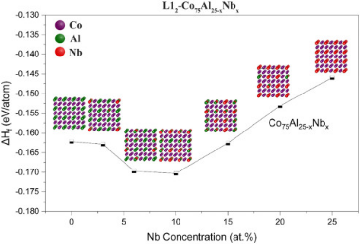
圖12. Enthalpy formation energies of the L12-type Co3(Al, Nb) phase as a function of Nb concentrations.
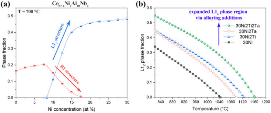
圖13. (a) Phase fraction of the L12 structure and the B2 structure as a function of Ni concentration in the Co-10Al-3Nb-xNi alloy. (b) L12 phase fraction as a function of temperature among Ti- and Ta-alloyed Co-10Al-3Nb-30Ni-based alloys.
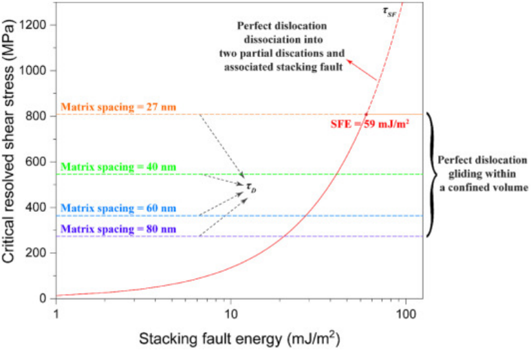
圖14. The critical resolved shear stress required for perfect dislocations gliding through the narrow matrix channels and dissociation into partial dislocations is plotted as a function of the stacking fault energy of the matrix phase. Various matrix spacings are considered in this plot to reveal the extra resistance from the geometric constraint to the movement of dislocations.
免責聲明:本網站所轉載的文字、圖片與視頻資料版權歸原創作者所有,如果涉及侵權,請第一時間聯系本網刪除。

官方微信
《中國腐蝕與防護網電子期刊》征訂啟事
- 投稿聯系:編輯部
- 電話:010-62316606-806
- 郵箱:fsfhzy666@163.com
- 中國腐蝕與防護網官方QQ群:140808414


